
Two callouts can look nearly identical on a drawing and ask for completely different parts. The ASME GDTP Technologist exam knows this. Its rules, definitions and symbology section is worth 25% of the mark, and a good share of its questions turn on one word of a stem.
This page lines up the term pairs people mix up, says what each one means on a real job, and shows where the exam hides the slip.
Which GD&T terms do candidates mix up most?
ASME says the Technologist level tests the rules, definitions, principles and meanings of the symbols and modifiers, the functions and relationships of part features and geometric controls, and the calculations that come off a drawing. That is a vocabulary exam with arithmetic attached.
The exam is 150 questions in 4 hours, closed book. You pass at 74% with at least 50% in every section. Our video on datum features, reference frames and targets covers the first pair below in motion.
 GD&T Datums Explained: Datum Features, Reference Frames and Targets (ASME GDTP Y14.5-2018) Watch on YouTube · CertCrafter
Here is the short version, before the detail.
| Pair | What separates them | What the exam does with it |
|---|---|---|
| Datum plane and datum axis | Where the datum feature symbol sits | Offers “both planes” or “both axes” |
| Profile of a line and profile of a surface | Two dimensional sections or the whole surface | Treats the line control as a surface control |
| Overall flatness and per unit flatness | Whole face or any small patch | Adds the two values together |
| Runout reading and diameter | High minus low on the indicator | Halves or doubles the sweep |
| Regular and irregular feature of size | Cylinder, sphere or parallel planes, or another shape | Says only cylinders can be datums |
| Simultaneous and separate requirement | Default or an explicit note | Swaps which one needs the note |
What is the difference between a datum plane and a datum axis?
The datum feature symbol is a framed letter on a leader. What it touches decides what it means.
Placed on the outline of a surface, on an extension line clear of the size dimension, or on a leader pointing at the surface, the datum feature is that surface and the datum derived from it is a plane. Aligned with the size dimension of a feature of size, or attached to its feature control frame, the datum is the centre feature: an axis for a bore, a centre plane for a width.
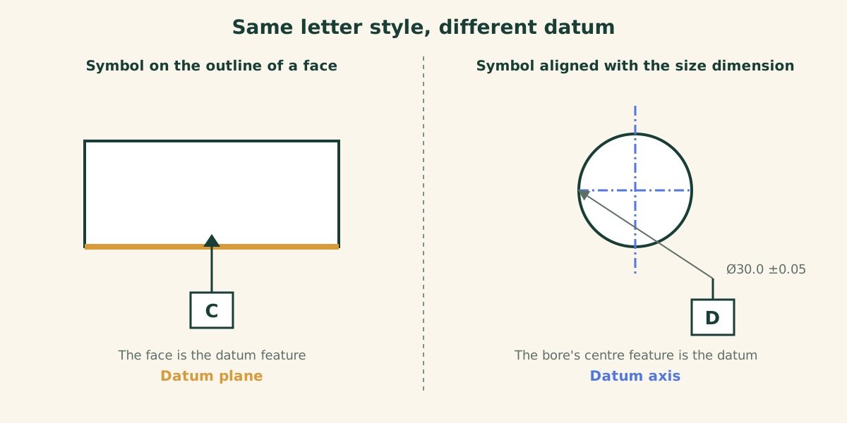
On a shop floor, this is a set-up decision. A face datum means the part sits on that face. An axis datum means the part is located by its bore, on a mandrel or an expanding pin. Misread one and the fixture holds the part wrong, then every position check that follows is measured from the wrong place.
The exam builds its wrong options from the same confusion. Expect “both establish an axis” for a symbol on a flat face, or “both establish a plane” for a bore. The correct reading is a plane from the face and an axis from the bore.
How do profile of a line and profile of a surface differ?
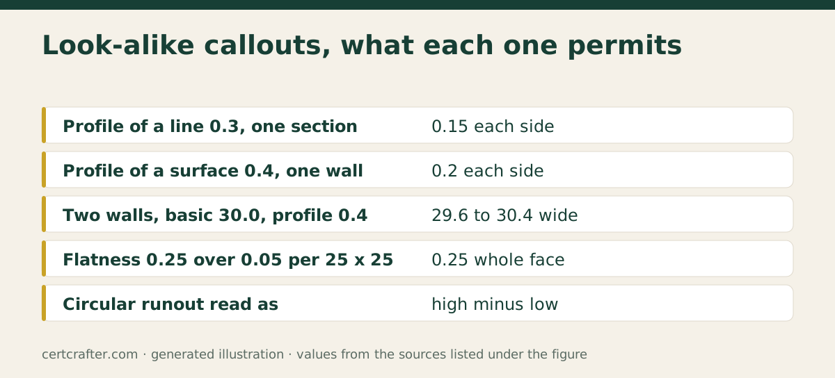
Profile of a line is a two dimensional control. At each cross section taken in the specified direction, the line element of the surface must lie within the zone, and every section is judged on its own. Nothing ties one section to the next. A rail with a curved top, toleranced with profile of a line | 0.3 | A | B, can twist or taper along its length without breaking the callout, because each section has its own zone, half the value each side of the true profile.
Profile of a surface is three dimensional. The whole surface must sit in one zone.
In industry practice this is a conversation with a supplier. An extruded part with a line profile callout is saying the cross section matters and the length does not. If the section-to-section relationship matters, the designer needs profile of a surface or an added form control. Inspectors who plot sections on a CMM and treat the result as a surface check pass parts the drawing never promised to control, or reject parts it allowed.
The trap in the exam is the option that says the callout controls the whole surface “exactly as profile of a surface would”. It does not. Watch for the option that invents a second envelope at twice the value, and for the one that claims a line profile cannot reference datums. It can.
What does a profile zone with no datum reference allow?
A profile of a surface with no datum feature references makes a zone that follows the true profile but is not tied to any datum reference frame. It controls the shape and the interrelationship of the surfaces within it and leaves the whole feature free to sit anywhere. With no unequal disposition stated, the zone is split evenly, half the value each side of the true profile.
Worked example: two walls of a slot
A slot is defined by a basic width, and both walls carry profile of a surface | 0.4 with no datum references. Ignoring form error within each wall, what widths does that allow?
- Split the zone: with no unequal disposition stated, the value is divided in two, half each side of the true profile.
- Each wall can move that half outward or inward, and there are two walls.
- Both outward: basic width plus half plus half, so basic plus the full zone value.
- Both inward: basic width minus half minus half, so basic minus the full zone value.
The width runs from basic minus the callout value to basic plus the callout value, a total variation of twice the callout value. Candidates who apply the split to one wall only get a range of one zone value in total. Candidates who give each wall the full value get a range twice as wide as the callout allows. Both are wrong, and both appear as options.

What is the difference between overall flatness and per unit flatness?
A two segment form callout gives a limit for the whole surface and a tighter one for any smaller area of a stated size. Take flatness | 0.25 over flatness | 0.05 / 25 x 25.
The first value is the total flatness allowed across the entire face. The second applies within every 25 by 25 area anywhere on that face. The face may wander gradually along its length while staying locally smooth.
The per unit value is a refinement inside the whole face zone. It is never added to it, so the two values do not sum. It does not let the inspector pick one convenient patch either: the requirement holds for every area of that size, including the worst one.
On a job, a sealing face or a ground reference surface often needs both. A gasket cares about the local patch, the assembly cares about the whole plane. The per unit segment can only tighten.
How is runout read, and why do people halve it?
Runout is full indicator movement: the total travel of the needle in one revolution, the highest reading minus the lowest. If the needle rises above zero by one amount and falls below zero by another, you add the two amounts. The result is then set against the number in the frame, as in circular runout | 0.04 | A-B.
Three slips fill the wrong options. The largest single reading ignores the low side and always understates runout. The difference of the two magnitudes subtracts as if both readings sat on the same side of zero. Doubling the movement assumes a diameter reading needs converting. The indicator already reads the full variation of the surface.
Where the indicator was zeroed makes no difference, because only the total travel counts. Zero it on the high point and the needle then only falls, so the runout is simply how far it fell. Circular runout is checked at a single cross section. A common datum A-B means both journals are simulated together to give one axis.
Where else do look-alike terms show up?
A feature of size has a size you can measure, such as a bore or a slot. A regular one is a cylinder, a sphere or a pair of parallel planes. An irregular one is a directly toleranced feature, or a collection of features, that can contain or be contained by an actual mating envelope other than those three. A moulded contour defined wholly by basic dimensions and controlled by profile is irregular, and it can be a datum feature. So a callout that labels such a contour as datum feature B is legal, and “only a cylinder, a sphere or a width may be a datum feature” is the trap answer.
Two hole patterns that share identical datum references, in the same order and with the same modifiers, are one simultaneous requirement by default. Writing SEP REQT beneath the frames breaks that default so each pattern is verified in its own reference frame. The exam swaps the two notations: simultaneous is the default and needs no note, separate is the exception that must be stated.
Last, a dated pair. Y14.5-2018 removed concentricity and symmetry as tolerance types. They appear on the exam only as wrong options or in questions about what replaced them. The 78% pass mark that circulates is from the older Y14.5-2009 exam; the 2018 Technologist exam is passed at 74%.
How do you study term pairs?
Write each pair on one card with the one-word difference underlined. Then say a callout aloud as a sentence before you answer anything about it. Ask what the symbol touches, whether the control is a section or a surface, and whether the number is for the whole or for a patch.
Try the free sample on the quiz page first. For the full set there is the practice test bundle with six tests, the certification guide, and the hub of guides. Two earlier posts pair well with this one: what the rules and symbology section tests and the ten most common mistakes.
Your next step: pick three callouts from a drawing at your own desk and write down, for each, whether the datum is a plane or an axis and what the number applies to.
Comments
Comments are read by a person before they appear. How we moderate.